Introducing: The Custard Antenna
In a previous post, I loaded up a bowl of custard with an ATU. I called the post “Custard Antenna” however, really, it should probably have been titled “Custard dummy load” – with both antenna wires immersed in the bowl, the custard was no doubt mostly behaving as a resistor, with any pickup or radiation likely to be on the wires – though removing the wires did also prevent it from receiving, which does make me think it might be behaving as a somewhat lossy loop antenna. I chose this format not because I thought it would work as an antenna, but because the whole thing was inspired by the phrase “tune a bowl of custard” so I wanted to take it literally.
Anyway, this post is about making an actual custard antenna. In truth, when I started this I wasn’t actually sure how to do it. I thought about using guttering as troughs but it would be awkward, especially since I couldn’t quite think of a way to elevate the antenna to avoid the power simply coupling into the ground.
The Plan
The design I settled on was clear plastic tubing, with an inside diameter of 12mm – I figured this is wide enough that the fairly thick antenna fluid custard can be poured down it, but small enough that it won’t be so heavy that it’s impossible to get up in the air.
Taking some rough measurements from a box of antenna fluid custard, I calculated the density to be 1094Kg/m^3 – just a bit more dense than water – which makes sense. This means 5m of 12mm tubing would contain about 600g of antenna fluid custard – which I think should be light enough to be supported by my portable antenna pole. This is a good start!
My plan was to make a vertical for the 20m band using the tube of antenna fluid custard. This leaves the question of what to make the radials out of. Custard could also be used for the radials, and this would make it very much a custard antenna. On the other hand, using regular wire radials would allow swapping a wire element out for the custard for direct comparisons – I decided on the latter.
Interestingly, someone on Twitter pointed out that water actually has a very low velocity factor – in the order of 10% – and pointed out custard could be similar. Velocity factor is a measure of how fast electromagnetic waves move down a conductor or waveguide. It is quoted as a fraction or percentage of the speed of light in a vacuum. Typical values might be 70% for coaxial cable or 95% for balanced feeder. This matters when building an antenna, since a 1/4 wave element needs to be 1/4 of the wavelength in the conductor, not 1/4 of the wavelength in free space in a vacuum (which is how the wavelengths are typically quoted). Practically, if true, this could result in a very short (and probably very lossy) antenna for the wavelength.
Preliminary Experiments
One interesting question would be how different variants of custard compare, electrically. I already have 3kg of custard left over from a previous experiment, so unless any others are significantly better, that’s most likely what I’ll use. It’s still worth testing other variants though. For these experiments, I used tins of custard, since the range was greatest.
Tesco Custard
This is what I used last time to tune a bowl of custard, and have 3kg of left. It’s the baseline to compare to.
Tesco Low Fat Custard
This is the low fat variant of the baseline. It is actually higher in sugar which could make things interesting and potentially behave slightly differently.
Stockwell Custard
This is lower in sugar and fat than the baseline, and also cheaper. Again, it may behave differently.
Results
With the exception of the condensed milk, which seemed to have relatively high resistance (measured using antenna analyser placed across a 1M long tube of the substance under test), the custards all behaved similarly electrically. Some exhibited more yellowness than others (definitely an important parameter). Resonances seemed to broadly match what I’d expect for wire of the same length, which somewhat throws out the velocity factor idea (I’ve since learnt velocity factor has more to do with the insulator than it does the conductor so this actually makes sense)
Condensed milk tended to leak out the end of the tube where the wire entered, which was not a problem with the rather thicker custard.
Going Full Scale
The time came to build a full size custard antenna. I took 5m of the plastic tubing, placed on end into a box of antenna fluid custard, and started sucking on the tube, like a huge straw. At first, it seemed to be working well. The problem was, the more custard entered the tube, the harder it became to draw the antenna fluid custard up the tube. In the end, I got about 2.2m of custard into the tube. I decided this was going to have to be enough, and proceeded to attach the tube to a telescopic antenna pole. I then laid out some wire radials, partly because it was easier, and partly because then I could more directly compare a wire vertical to a custard one.
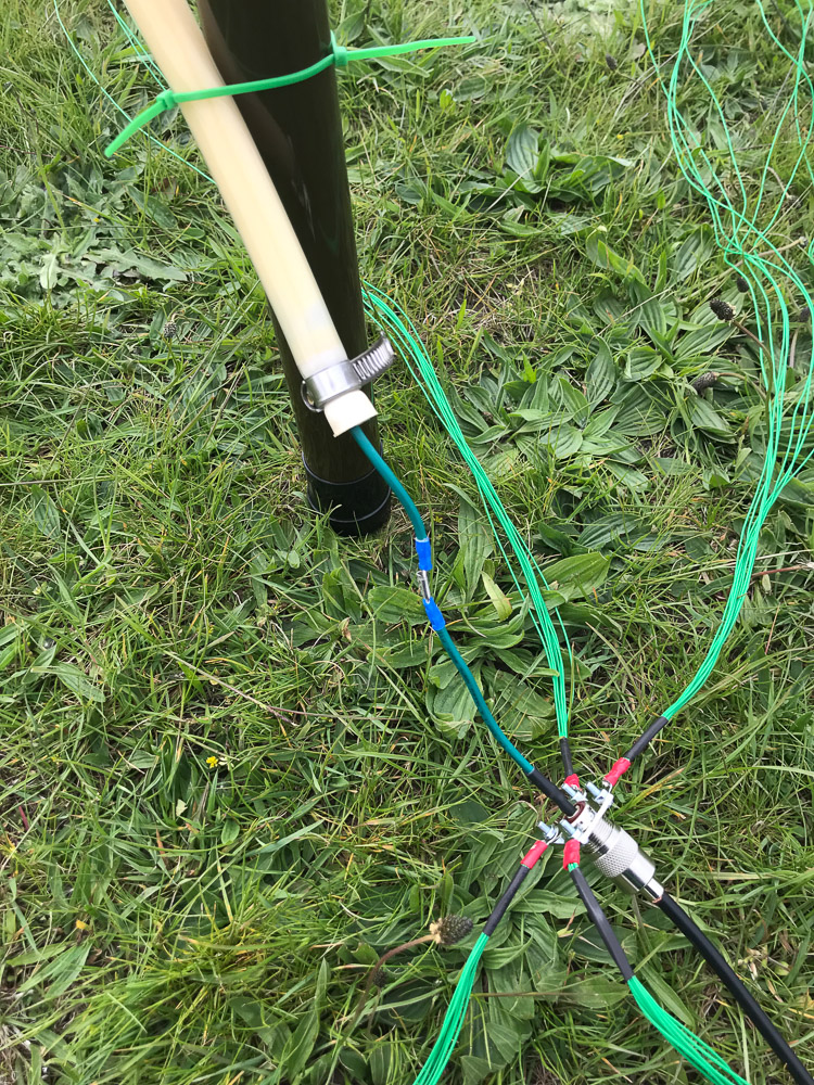
The Custard Feedpoint – the green wire enters only as short distance into the tube
The next step was to attach an antenna analyser and see how well the monstrosity my creation functioned as an antenna. To my surprise, it was not resonant in any frequency below about 150mhz, but above that, was resonant on many frequencies. The frequency response was described by one person on the London Hackspace Radio IRC channel as “gloopy”
The frequency response is… Gloopy… 3:1 SWR ratio – not great but just about usable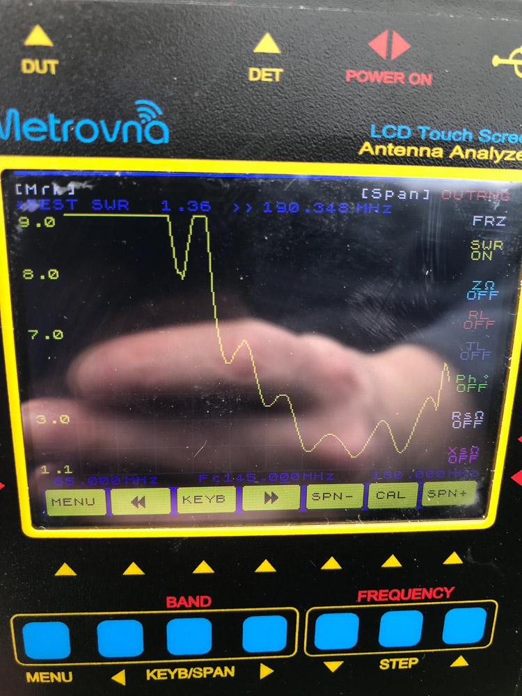
Unfortunately, I didn’t have any equipment with me for the 2m/145MHz band (actually I did, but didn’t need have the necessary coax adaptors), so I swapped to a more regular wire radiating element and made some 20m HF contacts (mostly FT8, a couple of SSB voice ones as well) to avoid the trip out to the nearby field.
Custard’s Last Stand
The following day, I returned with much the same setup, but this time also with a Yaesu VX-7 handheld and after putting up the pole again and laying out some (longer) radials, I tried to open a local repeater, GB3EL – and it worked! A few test calls later, and I realised I was able to consistently open the repeater and get a signal of about S6-7 back from it on the custard antenna. Just to test, I disconnected the custard and got nothing- so the radials and short stub of wire at the feedpoint were not enough on their own – the custard was clearly radiating!
After this, I switched back to a normal antenna – I had proven the concept and wanted to use the limited daylight left for more usual contacts. I didn’t feel like wasting too much time on what I suspected to be an inefficient 2m antenna in an area where 2m isn’t always very effective.
Analysis and Conclusion
It took me a while to figure out what was actually going on here – the custard seemed to be resonant on a much higher frequency than its length would suggest – either the speed of light is faster in custard – opening up a whole new branch of custard physics, or something else is going on. As cool as new custard physics would be, I think there’s a more rational explanation.
A brief detour into antenna theory
Before I carry on, a brief word about impedance of antennas. Impedance is the combination of resistance and reactance. Resistance affects all frequencies equally (including DC) whereas reactance is frequency-dependant. Reactance also introduces phase shifts. Reactance is caused by capacitance and inductance. We can ignore the reactance here because while it is important to the overall matching of the antenna, it does not play much of a role in the actual losses in the system. In other words, when I talk about resistance here, I really do mean resistance – I’m not misnaming impedance!
A simple model of the losses in an antenna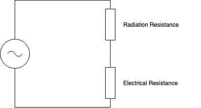
Back To The Main Topic
I suspect what’s actually going on here is that the custard is quite lossy – so the RF only actually “sees” the bottom part of the antenna – in effect, it behaves like an antenna made of high resistance wire – the lower part provides a combination of electrical and radiation resistance, but as you travel up the column of antenna fluid custard, the electrical resistance takes over until eventually there is basically no radiation. Modelling it in the same way gives us something like this: Model of “losses” in a custard antenna system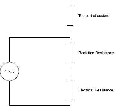
Practically, this means that while the custard works as an antenna, it cannot make antennas for lower frequencies since the losses are too great, and the top part of the custard simply doesn’t take part in the radiation.
In summary, Yes, you can use custard as an antenna, no I wouldn’t recommend it unless it’s all you have. If it is all you have though, and you need to get a signal out on about 145MHz, sure, go for it!