GB4LHS Special Event Station
Over the weekend, I operated a special event station, GB4LHS to celebrate the London Hackspace reopening in Wembley, and also to demonstrate amateur radio to visitors at the open day. Some things worked really well, other parts of the setup could really have done with improvement. In this post I hope to describe the details of this.
Some Statistics
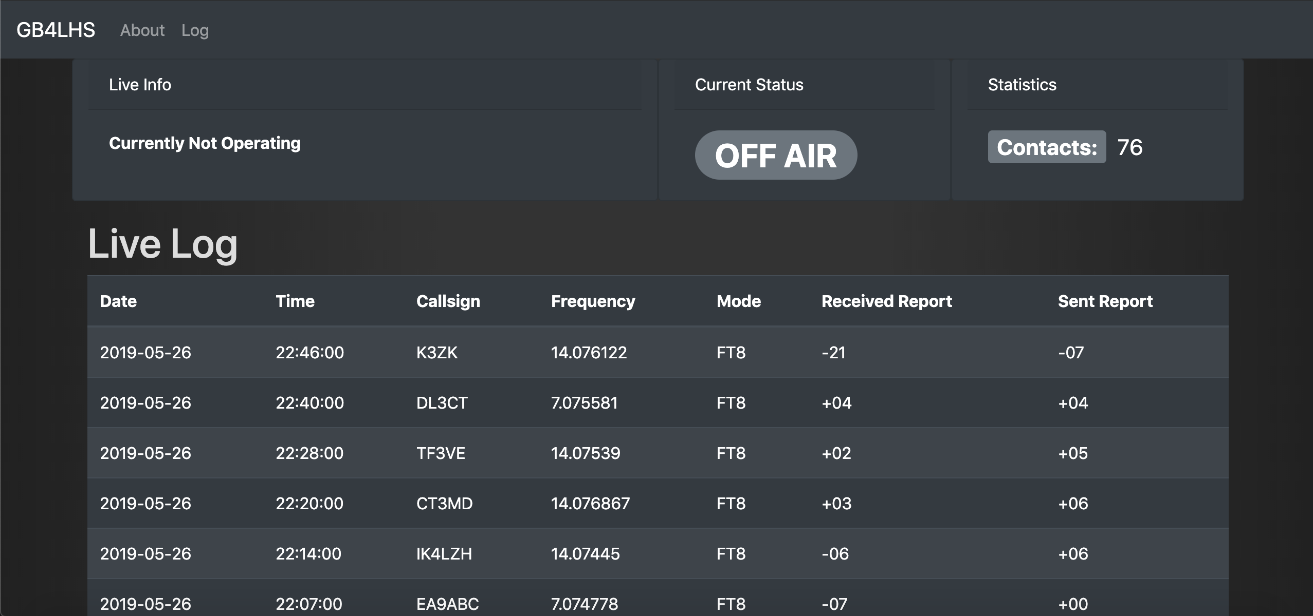
- Total QSOs: 76
- FT8: 68
- SSB: 8
- By Band:
- 17m: 20
- 20m: 20
- 40m: 36
- Countries Worked: 36
- Most Contacted: Federal Republic of Germany (13 QSOs)
- Time between first and last QSO: 23 hours
I have actually operated a special event station once before – I organised GB50SWN back in 2007 for JOTA. At the time I only had a foundation license, however with the (mostly quite distant) supervision by the full license holder, I made a total of about 4 contacts over two days. I comfortably beat that “record” at least! I’ll admit I actually set myself a slightly higher target for this event of 100 QSOs – but I’ll take 76 as close enough. Now I think about it, I might actually have got a few more if I had managed to get set up earlier and therefore got more sleep the night before, hence probably started again earlier.
I was probably most impressed by the 40m FT8 contact into Australia, and the 40m SSB contact into Kazakhstan. I was putting out 30W on FT8 and 100W on SSB. What’s interesting is both of these would have been towards the end of the dipole antenna – and therefore not in the most sensitive part of its radiation pattern,
The Setup
I decided to construct a variant on a fan dipole for this event, supported by the building at one end and a telescopic pole at the other. Google Earth suggested I had about 22m to play with – so enough space for a 40m band dipole. This deserves a whole section to itself, so I’ll discuss that more later.
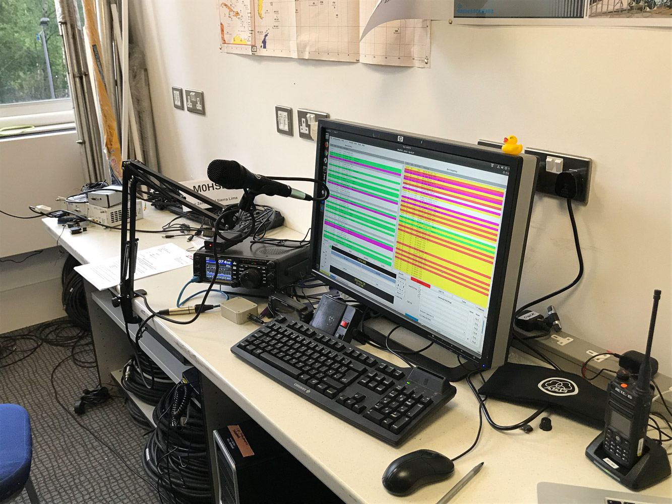
I fed this with my Yaesu FT-991A – I decided to use this rather than the Hackspace club’s FT-450 because it has a more modern receiver, and also because it has a built in voice recorder, so I could record CQ calls and play them back, saving having to speak so much. The FT-991A also has a built in sound card for data modes, however I ended up not using this due to incompatibilities with the computer I was using. Instead I used a MiniProSC I had with me in case I decided to use the FT-450.
In order to look more impressive, be easier to work with, and in case there was an opportunity to send greetings messages, I decided to use a microphone mounted on an inexpensive boom arm, and a keyboard pedal for push to talk. I fairly hastily built a cable to wire this into the Yaesu 8-pin microphone socket – an easy task as long as you realise Yaesu call pin 1 what I would call pin 8 on the 8P8C connector. The microphone I chose was the relatively inexpensive AKG P3S – I have always liked AKG audio equipment and this did not disappoint – I received compliments on my audio quality from all the SSB contacts I made. I also used AKG K240 MKII headphones for some contacts. I have had these headphones for a few years now and they’re fantastic – I can wear them for hours without them getting uncomfortable, and they are well built (I can be quite hard on my equipment!) with a removable cable.
I did try using an external speaker, but it turned out to be worse than the one in the FT-991A, so ended up using a mixture of the built in speaker and headphones.
Live Status website
For logging, I used Cloudlog written by 2M0SQL – I spent quite a bit of time before the event fixing various bugs I hit in my setup. Overall though, it was a very useful tool and mostly worked well.
In addition to this, I had set up a live log website, with some auto refreshing (using JSON XHR requests) stats such as current frequency and the last 10 contacts logged. The idea was it would make it easier for people to catch me on the dial. Although this was hastily put together, it worked well though I don’t know how much use it got. I can see myself reusing this code in future. It was a flask app on top of the cloudlog database.
What Went Well (The Rig)
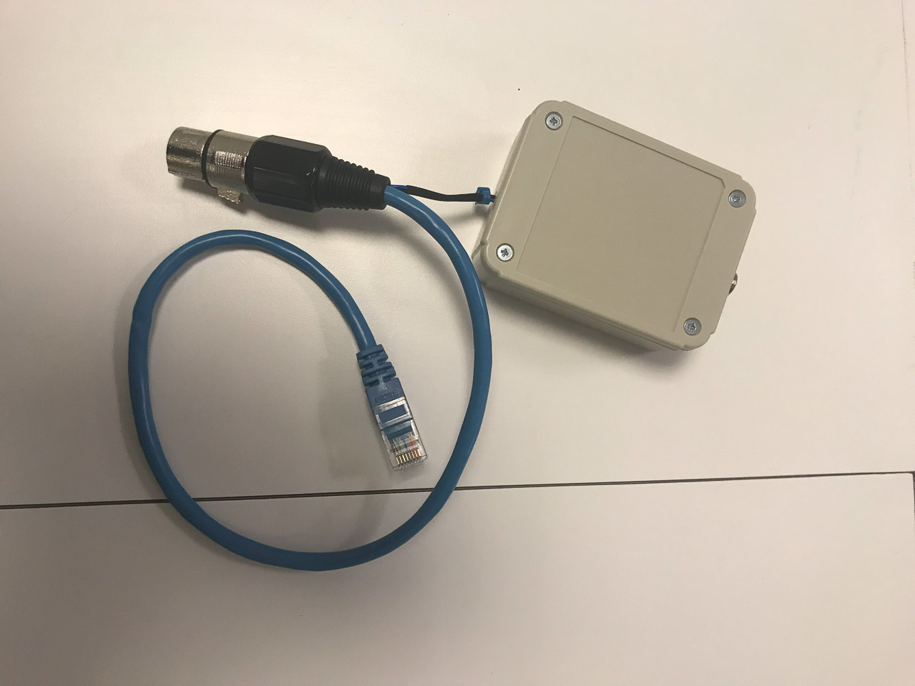
XLR to 8-pin microphone plug. I didn’t have any line sockets for 6.35mm jacks, so put a panel socket in a box.
The overall setup was quite successful, with plenty of contacts made, and plenty of compliments on audio quality. The one thing I wasn’t entirely happy with was the receive audio – I really needed headphones to hear the often weak or noisy signals, but I was reluctant to use them during the day when people were around because then it wouldn’t have been much good as a demo. I’ll mention some ideas I have for improvements here later in the post.
Once I figured it out, the 6m telescopic fibreglass pole worked well to support one end of the antenna, and the other end was tied to a conveniently located eye bolt inside a window.
What Didn’t Work So Well (The Antenna)
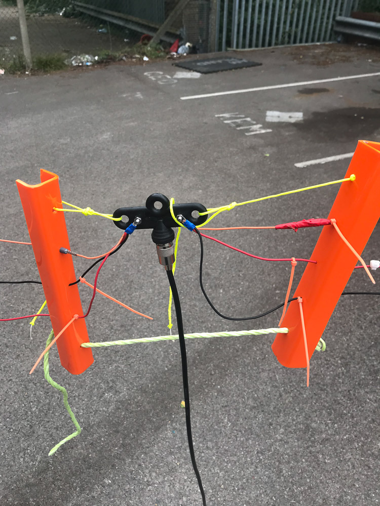
An early-ish iteration of the feedpoint. Note the ferrule used to keep the tension on the crimp connector low, and also the bends in the acrylic for strength.
I had the idea of making a fan dipole with laser cut separators for the 40, 20 and 17m bands. A fan dipole is a brilliantly simple, yet effective antenna. Essentially, you build multiple dipoles for different bands, and connect them all to the same feed point. The radio waves tend to use the most resonant wire (I guess because it’s the lowest impedance). I chose this design because I didn’t want the inefficiency or hassle of an ATU. Further, previous experiments with custard proved unsuccessful on the HF bands so that wasn’t an option. The idea of the laser cut separators was to keep the wires fairly close together, to keep the ends as high as possible.
This worked better in my head than it did in reality. The initial design for the separators had a tendency to snap under the tension of the antenna. This was resolved by bending the ones at the ends to increase strength. Initially, I planned to linear load the 40m element to shorten the antenna slightly. As it turned out, this just complicated things, and I really didn’t need to. After much trial and error (mostly error), I got it nicely tuned on three bands. One thing that really helped here was an idea from fellow Hackspace member Simon to put the wires on separate crimp connectors, allowing easy disconnection of the wires individually for tuning, then reconnection for final adjustment and operation.
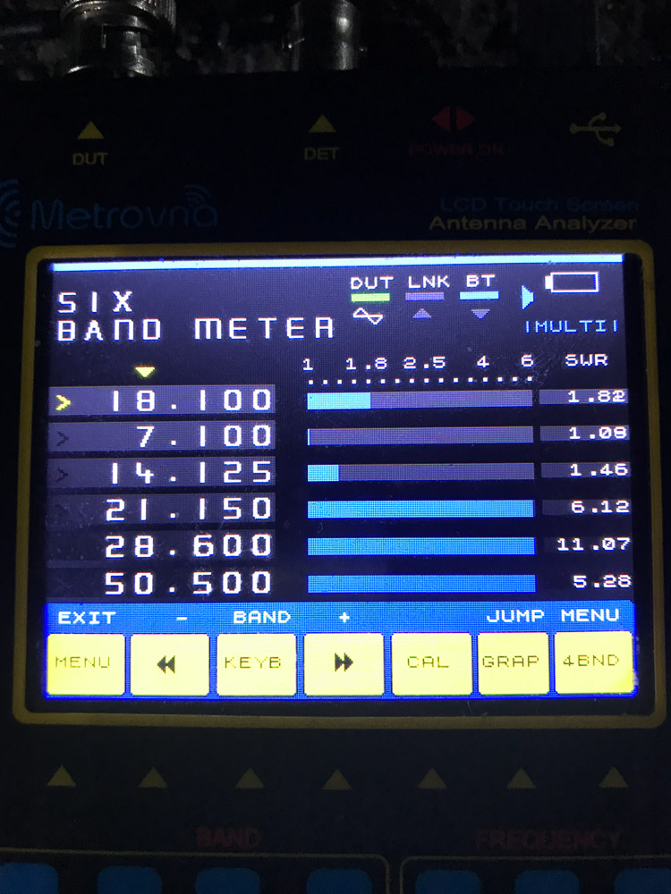
It tuned! Or did it?
However once up in the air, and connected to the intended coax run, the resonance on all bands dropped, making it rather less good (except on 17m where it improved if anything):
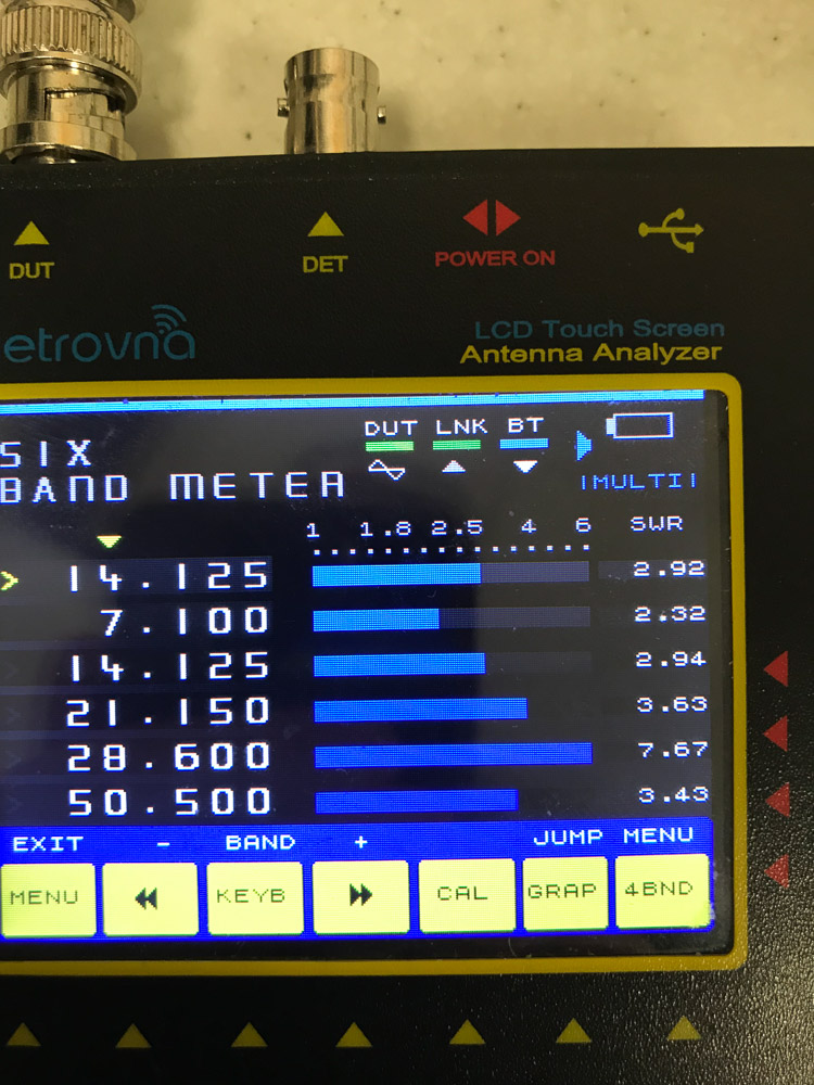
Results after bringing the coax inside. I just realised 18.1MHz isn’t here, but it was actually pretty close to 1.0:1.
I think there are a few things going on here. Firstly, I suspect the wires twisted a bit, and probably got closer together. Secondly, I had attached a longer piece of coax, with chokes on which were not present on the piece I used for testing. Thirdly, the coax was coming off at a bit of an angle, which probably tweaked things a bit.
In the end, I decided to run with it. I figured the rig ATU could probably make up the rest, and in any case, a 3:1 SWR ratio isn’t completely terrible. The rig seemed happy enough on most frequencies, so I wasn’t too bothered. The only downside was SWR got a bit too high on the upper part of the 20m band. I ended up cutting that element from slightly thinner wire, and I believe thinner wire tends to have a narrower bandwidth, so the SWR went up quite sharply above about 14.200. It was usable on the lower part of the band for FT8 though.
As it turned out, the antenna was most resonant on the 17m band, and the built in ATU, while effective on 40m, actually made things worse on 20m! In any case, radio waves got out. In future, I think a more traditional fan dipole with rope or twine between the elements might be more effective – I believe the close spacing of my laser cut spacers made it too sensitive when tuning and too prone to twisting.
One thing I definitely underestimated with this was the amount of tension in the top element – and therefore the pole and some of the spacers. In the end, the top of the pole ended up (mostly accidentally) tucked behind the lamp on top of the lamp post, which provided extra support and stopped the pole from bending nearly as much as it otherwise would have done. It took a considerable amount of force to pull the top of the antenna level-ish – I’m not sure if this is inherent in fan dipoles or if it’s down to my laser cut spacers – but it was definitely more than I expected.
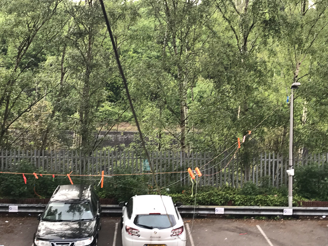
The antenna, strung between the building (via an open window) and a fibreglass pole tied to the lamp post
In the end, I could easily have got away with the ends being lower down, so I really didn’t need the extra complexity of the laser cut spacers. That said, they did give it a more Hackspace look!
One other thing not antenna-related that didn’t go so well was the CAT control interface. As well as having to use an RS-232 cable for this, I also found rigctld regularly stopped responding and timing out with the rig, or exited. This meant I had to restart it more than I’d like. rigctld was being used by both WSJT-X for FT8 and also a script updating cloudlog. A few other club members told me they have seen similar issues on that machine, so it’s likely it will get a fresh OS install in the near future.
Things To Try Next Time
Apart from tuning the antenna better, the biggest thing I would improve is the receive audio setup. Next time I do something like this, I want to have some decent speakers hooked up to the rig, but with an audio splitter so I can still use headphones to get some isolation and hear the weaker signals. One of the biggest problems I had was people having (loud) conversations right outside the (open) door which did not make the high RF noise level any easier to work with. This way, visitors can still hear what’s going on, while the operator can actually hear the more difficult signals.
I had a DMR rig handy, but didn’t really do much with it, so apart from showing off a pi-based hotspot a bit, I could do more with that.
One idea I had but decided against on this occasion – mostly to avoid scaring visitors off – is live streaming the audio from the transceiver and maybe even some video. Video probably isn’t the greatest plan since people are probably reluctant to go anywhere near a live video camera, but audio streaming might be fun.
I’m not sure it really counts as an improvement, but I’m told I need to have a custard antenna at the next open day. I guess time will tell if I actually do that or not.
Conclusion
Overall it was a very fun day, and I’m keen to do it again. A few tweaks (notably a setup allowing me to actually hear the signals) would make a big difference. I was, as ever, pleased with the performance of the Yaesu FT-991A, and the voice memory was indeed very handy for easily calling CQ.
The antenna wasn’t as good as I hoped, but it still got signals out, and I learnt a lot I can apply in future to make it less of a headache, so overall I guess that’s a good thing.